Installation box spacing, hole size and depth: the numbers by model
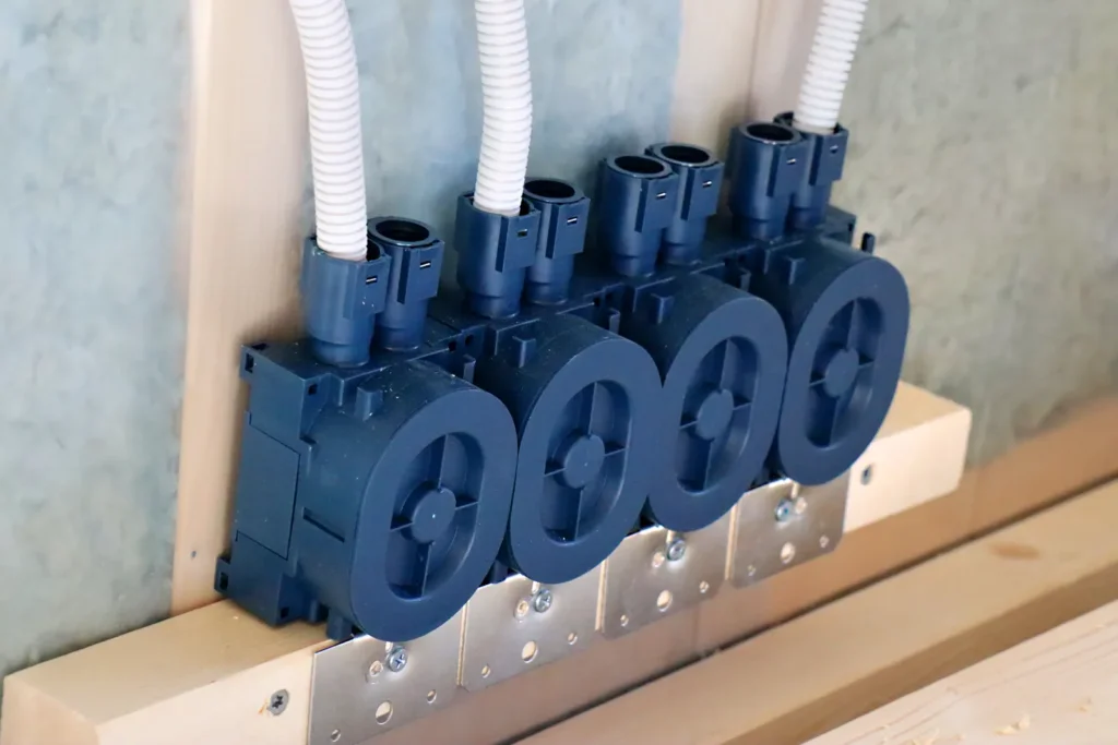
Short answer: Glob-el Universal-series installation boxes are ganged side by side at 71 mm centre distance with connector ETM332S, or at 84 mm with ETM333S. Device screws sit 60 mm apart (M3) on most models, 67 mm on ETM398SF and ETM931S, and 70 mm (M4) on the ceiling boxes. Most boxes are 60 mm deep. Shallower options run from 32–40 mm (ceiling box ETM002S-4) to 45 mm internal (ETM750S).
The tables below list each model, with the catalogue page for every number. Page numbers refer to the printed page numbers of the Glob-el catalogue 2026.
In local terms, this article covers the installation box: Hohlwanddose or Installationsdose in German, inbouwdoos in Dutch, apparatdosa in Swedish, kojerasia in Finnish, indmuringsdåse in Danish and veggboks in Norwegian. Our terminology map for European buyers explains how these names relate.
How far apart are two boxes side by side?
71 mm centre to centre with connector ETM332S, or 84 mm with ETM333S. The connector sets the distance, so it doesn’t depend on marking out by hand.
| Need | Part | Centre distance | Source |
|---|---|---|---|
| Standard multi-gang row | ETM332S connector | 71 mm | Catalogue 2026, pp. 37–38 |
| Wider row | ETM333S connector | 84 mm | Catalogue 2026, pp. 37–38 |
| Solid wall, no adapter | ETM680S | 71 mm (c/c) | ETM680S specification sheet |
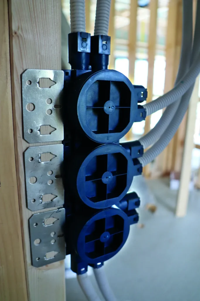
Before you order, check the distance against the frame of your switch and socket range. Our article on 60, 67 or 71 mm centre distance explains the difference between screw spacing and box spacing.
Open or closed between ganged boxes?
Both versions exist. The 71 mm and 84 mm frame extensions come open (ETM332S, ETM333S) or closed (ETM332SC, ETM333SC) (catalogue 2026, pp. 67–68). Which one a multi-gang position needs follows the installation rules where the building stands. A typical case is a row of boxes behind a TV with power, data and coax in separate conduits. The box material is halogen-free PP, glow-wire tested at 850 °C (IEC 60695-2-11) (catalogue 2026, pp. 31–32).
What is the device screw spacing?
60 mm with M3 screws on most models. The exceptions are 67 mm on ETM398SF and ETM931S, and 70 mm with M4 screws on ceiling boxes ETM002S-4 and ETM834S. The screw spacing decides whether a switch or socket mechanism fits the box. The box spacing decides whether a multi-gang frame fits.
| Model | Wall / use | Device screws |
|---|---|---|
| ETM336S | Timber or metal stud, single board | 60 mm (M3) |
| ETM610S | Timber or metal stud, double box | 60 mm (M3) |
| ETM613S | Stud wall, steel plate, 1½ box | 60 mm (M3) |
| ETM742S | Timber stud, large box with turnable inner ring | 60 mm (ST2.9) |
| ETM398SF | Metal stud | 67 mm (M3) |
| ETM220S-1 | Panel wall from 6 mm | 60 mm (M3) |
| ETM750S | Hollow wall or cast-in | 60 mm (ST2.9) |
| ETM002S-4 | Ceiling | 70 mm (M4) |
Source: Glob-el catalogue 2026 and product data sheets.
What hole size does the box need?
It depends on the model, and only some models need a drilled hole at all.
- Stud-mounted boxes (ETM336S, ETM610S, ETM613S, ETM742S, ETM398SF) are fixed to the stud with a steel plate before the boards go on: directly to timber studs, or with screws to steel studs. The boards are then cut to the box, rather than the box being set into a hole drilled through all layers afterwards.
- Boxes fitted from the front need a drilled hole of a specific size:
| Model | Wall | Hole | Source |
|---|---|---|---|
| ETM220S-1 | Prefabricated or hollow wall, panel at least 6 mm | 73–74 mm (Ø73 mm cutter) | ETM220S-1 specification sheet; catalogue 2026, pp. 51–52 |
| ETM680S | Brick, concrete, aerated concrete, Leca | 82 mm hole saw | Catalogue 2026, pp. 91–92 |
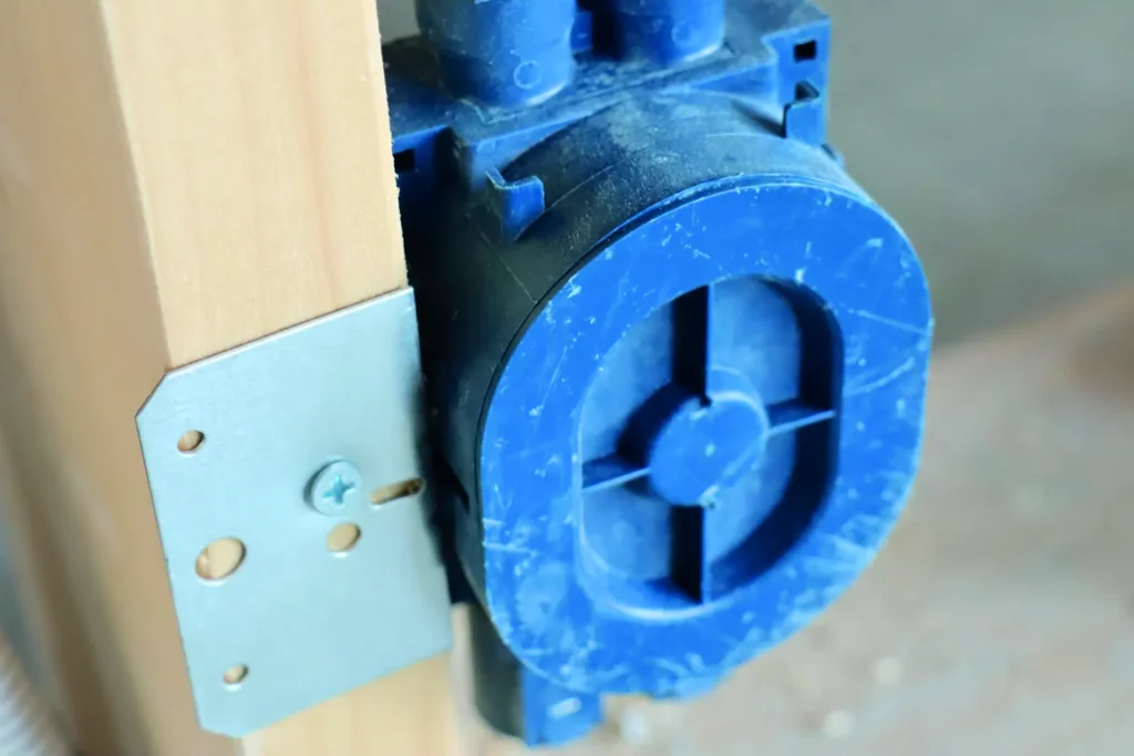
For every other model, take the hole or cut-out size from the data sheet and drawing rather than from a general rule. A hole that is too large leaves the box without a firm hold.
How deep are the boxes?
Most stud-wall and panel boxes are 60 mm deep. For thin walls and ceilings there are shallower models. For concrete ceilings there is a deeper one.
| Model | Depth | Use |
|---|---|---|
| ETM002S-4 | 32–40 mm | Ceiling, max. load 15 kg |
| ETM750S | 45 mm internal | Hollow wall or cast-in |
| ETM680S | 47–57 mm, adjustable | Solid wall |
| ETM336S / ETM610S / ETM613S / ETM398SF / ETM220S-1 | 60 mm | Stud and panel walls |
| ETM780S | 60.5 mm | Precast concrete element |
| ETM834S | 88.5 mm | Concrete ceiling |
Source: Glob-el catalogue 2026 and product data sheets.
Single or double plasterboard?
Check the box against the board thickness. The Universal series is made for single (12–13 mm) or double (24–26 mm) gypsum boards, but the model differs by board:
- ETM336S is the single-board version and ETM335S the double-board version (catalogue 2026, pp. 29–32; ETM335S/336S specification sheet).
- For steel studs, ETM398SF is made for a 12 mm board and ETM399SF for a 24 mm board (catalogue 2026, pp. 49–50).
- The ceiling box comes as ETM002S-4, -5 and -6 for single, double and triple gypsum (catalogue 2026, pp. 55–58).
- The steel fixing plates are also made per board: ETM642S–ETM645S cover single and double wall plates, including versions for the long side of a 1½ box (catalogue 2026, pp. 65–66).
What if the wall is OSB plus plasterboard?
Send us the build-up before you choose. Our stud-mounted boxes are documented for single (12–13 mm) or double (24–26 mm) plasterboard. Build-ups such as 10 mm OSB plus 12.5 mm plasterboard (22.5 mm) or 18 mm OSB plus 12.5 mm plasterboard (30.5 mm) fall between or outside those two ranges. For any other build-up, tell us the layers and thicknesses and we will check the fit model by model before you order.
Can I add conduit entries when boxes are ganged?
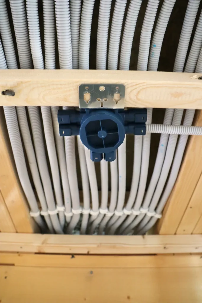
Yes. The Universal series has separate extensions for extra entries (catalogue 2026, pp. 65–68):
| Part | What it adds |
|---|---|
| ETM331S | Double extension, 2 × Ø16/Ø20 mm |
| ETM393S | Two-way extension, 2 × Ø16 mm |
| ETM389S | Triangle extension, 3 × Ø16 mm |
| ETM822S | Triangle inlet, 2 × Ø16 mm + 1 × Ø16/20 mm |
| ETM646S / ETM820S / ETM821S | Conduit entry 25 / 32 / 40 mm |
| ETM612S | Coupling bushes with tension relief for MMJ-type cables |
| ETM384S | Blind extension |
The large box ETM742S can also be connected to single Universal boxes on three sides (catalogue 2026, pp. 61–62).
Frequently asked questions
What is the drilling distance (Bohrabstand) between two installation boxes?
71 mm centre to centre when the boxes are joined with connector ETM332S, or 84 mm with ETM333S.
What hole saw do I need for ETM220S-1?
A 73–74 mm hole. The specification sheet recommends a Ø73 mm cutter, and the panel must be at least 6 mm thick.
Is there a shallow box for ceilings?
Yes. Ceiling box ETM002S-4 is 32–40 mm deep and carries up to 15 kg. ETM750S has a 45 mm internal depth.
Which box fits double plasterboard?
ETM335S is the double-board version of ETM336S, and ETM399SF of ETM398SF. For ceilings, use ETM002S-5 (double) or ETM002S-6 (triple).
Which box fits OSB plus plasterboard?
Our stud-mounted boxes are documented for single (12–13 mm) or double (24–26 mm) gypsum boards. For other build-ups, send us the layers and thicknesses and we will check the fit before you order.
Can ganged boxes be closed off from each other?
Yes. Closed frame extensions ETM332SC (71 mm) and ETM333SC (84 mm) are available alongside the open ETM332S and ETM333S.
Can the boxes be installed in cold weather?
The specification sheets for ETM335S/336S, ETM220S-1, ETM680S, ETM002S-4/-5/-6 and ETM761S give an installation temperature of −5 °C to +25 °C and a working temperature of −25 °C to +60 °C.
Will the box fit my switch range?
Most models use 60 mm (M3) device screws and 71 mm ganging; a few use 67 mm. Send us the range or frame you use and we will check it model by model before you order.
Send us your wall build-up and your switch range. Within one working day we’ll reply with the matching models, data sheets and drawings. → Send an enquiry
Local pages: Deutsch · Nederlands · Svenska · Suomi · Dansk · Norsk
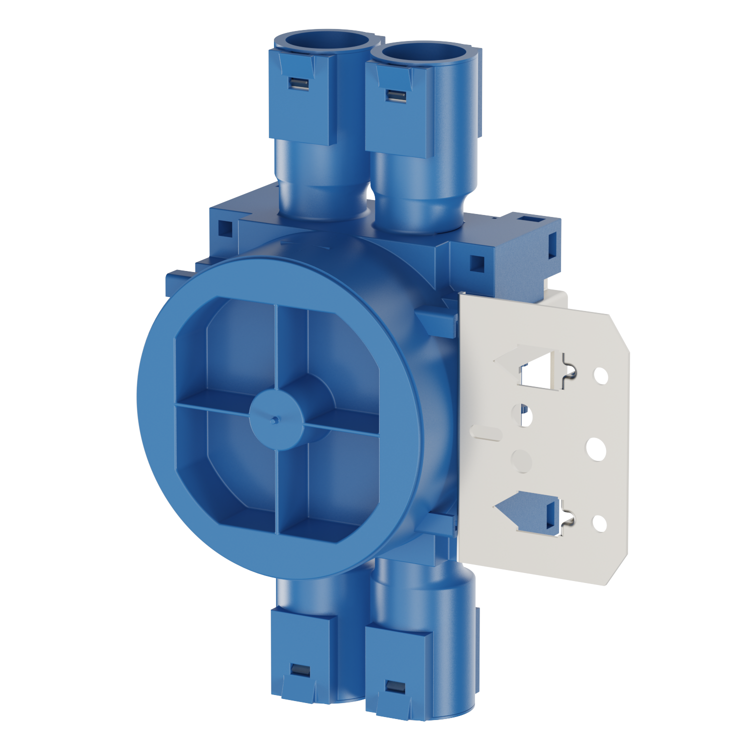
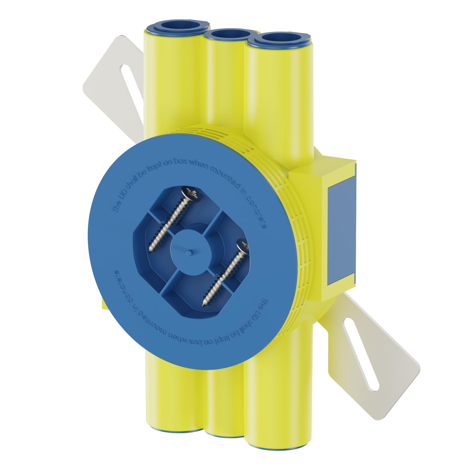
Models referenced in this guide
Related reading from Glob-el Power: How to install a Schuko socket module safely — a step-by-step view of fitting the device that the screw spacing has to match.